I quite enjoy making small RC tracked vehicles, and as an engineer I wanted to increase their capabilities - in speed. This means I need to know the torque-rpm-power graphs of the motors, which would allow me to size the motor to fit the vehicle. To create these graphs I needed a dynamometer. This project was only a partial success....

This is a simple inertial dynamometer - it has a large rotating mass and it measures the time it takes to get it up to a certain speed. If you know the inertia of the system, and measure the acceleration, then newtons laws state that you can know the torque being applied.
I didn't have any fancy gear - no rotary encoders, no precision anything, so I tried to make it up as I went along. I used an infared reflective-optocoupler to make an encoder, I used angle-grinder disks as a flywheel, and I used skateboard bearings and an m8 bolt. Just about all of those things have stories behind them.....
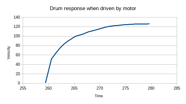
The main problem on this project was periodic noise due to misalignment
of bearings. This meant I had to average over an entire rotation to get
good results:
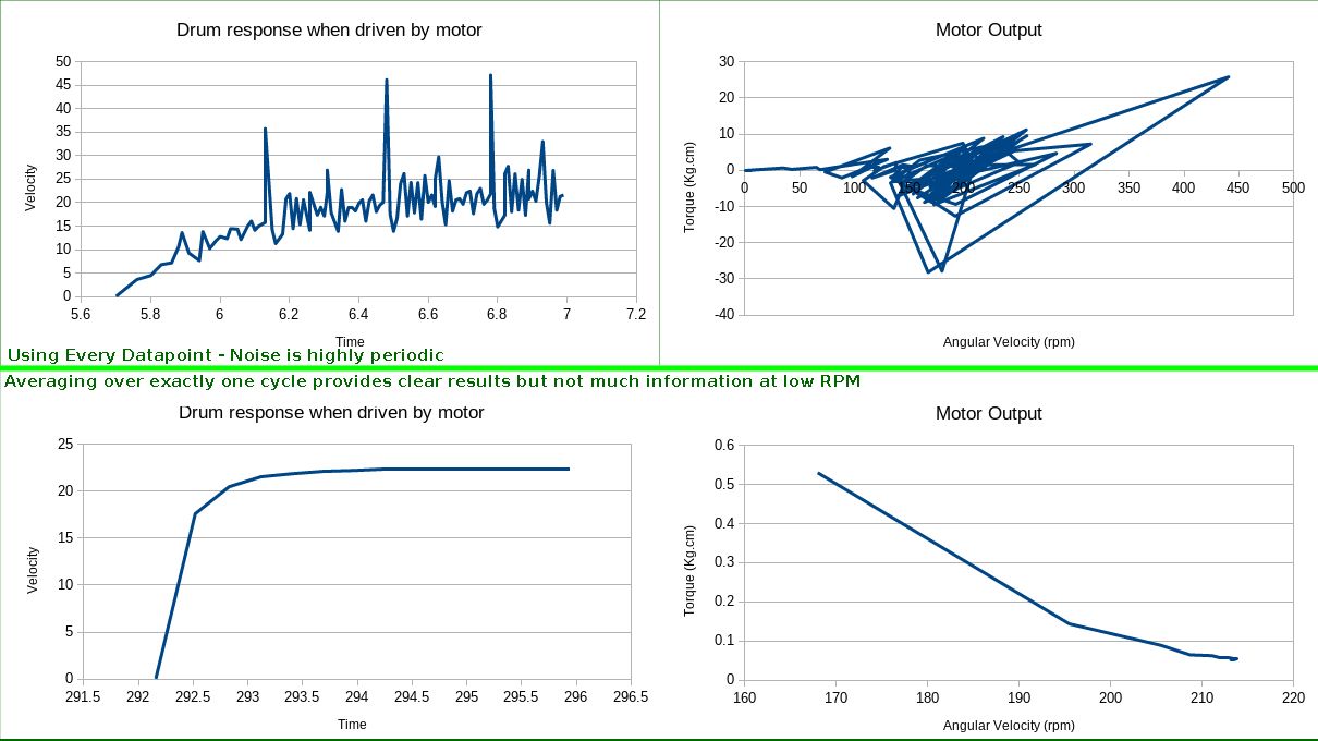 Yeah. Nah.
By mantaining a ring-buffer, you can still get the same number of
datapoints, all nicely filtered, but then the first rotation gives
garbage results. Unfortunately, most of the interesting stuff happens in
that first rotation.
Yeah. Nah.
By mantaining a ring-buffer, you can still get the same number of
datapoints, all nicely filtered, but then the first rotation gives
garbage results. Unfortunately, most of the interesting stuff happens in
that first rotation.
The rotary encoder
A simple rotary encoder is a slotted disk that interrupts a beam of light. Unfortunately I only had a reflective optocoupler where the LED and photodiode are mounted next to each other. This means that the signal is not perfectly binary. Similarly, due to variations in print tolerance and colouration of the angle grinder disks, a simple threshold to determine if there was a slot or not was not adequate.
After a bunch of experiemntation I arrived at a solution where I read
the sensor value with an ADC looked at the change in value from the
sensor. When it stopped going up and started going down it was an "edge"
and when it stopped going down and started going up it was another edge.
This was highly succesful. The code for detecting a tick ended up
looking like:
#define OPTICAL_SENSOR_NOISE_REJECT_BAND 20
int32_t encoder_tick_state = 0;
int8_t rising = 0;

bool is_encoder_tick() {
  // Returns true if the encoder has done a tick.

  // This function works using magic(tm). Actually, it looks to see if the signal is rising or falling and
  // emits a pulse when it approximately switches from one to the other.
  int16_t optical_sensor_raw = analogRead(OPTICAL_SENSOR_ANALOG_PIN);

  // Compute difference from previous tick:
  int16_t difference = encoder_tick_state - optical_sensor_raw;

  if (difference > OPTICAL_SENSOR_NOISE_REJECT_BAND) {
    // Value has risen more than the noise reject band, so this is a tick!
    if (rising <= 0) {
      rising = 1;
      encoder_tick_state = optical_sensor_raw;
      return true;
    } else { // We're moving in the same direction, so drag along our reference point
      encoder_tick_state = optical_sensor_raw + OPTICAL_SENSOR_NOISE_REJECT_BAND;
      return false;
    }
  }

  if (difference < -OPTICAL_SENSOR_NOISE_REJECT_BAND) {
    // Value has fallen more than the noise reject band
    if (rising >= 0) { // Signal was previously rising, so this is a tick!
      rising = -1;
      encoder_tick_state = optical_sensor_raw;
      return true;
    } else { // We're moving in the same direction, so drag along our reference point
      encoder_tick_state = optical_sensor_raw - OPTICAL_SENSOR_NOISE_REJECT_BAND;
      return false;
    }
  }

  return false;
}
I'm sure there are ways to optimize this, but it worked perfectly fine
for this situation. Plotting a graph of the various tick state and rising
variables show it to be detecting the edges very well:
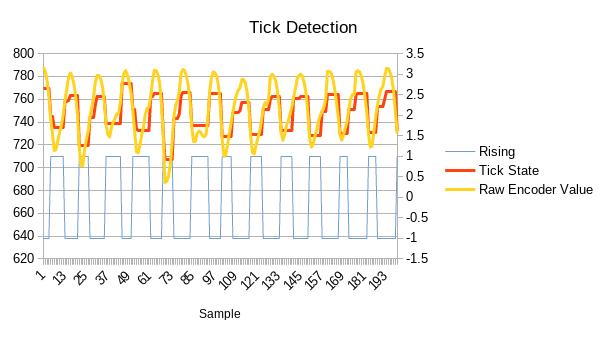 You can see the large variation in values reported by the encoder.
Mechanics
Make a shaft, put some flywheels on it. Sounds simple enough? Well.... I had a bunch of 608zz skateboard bearings, so I bought an M8 bolt to go through them. As I later realized, an M8 bolt is not a precision part, and so there is about 0.5mm of slop. This may not sound so bad, but it means that the flywheel is about 0.5mm off-center, and so there is a torque exerted by the flywheel dependent on the angle of the shaft. This is the main reason why this project is only a partial success - I couldn't get the torque ripple low enough, and so data is only useful when averaged over a complete rotation of the shaft. This means the data rate from this device is too low to measure the torque of the gear motors I was targetting.
One idea to offset the torque ripple was to make it take longer for the motor to speed up the flywheel. This way I can still average over the duration of an entire turn (and filter out the noise), but get enough data to be useful. So I put in a gear-train. Unfortunately as well as multiplying the inertia by 4, it also multiplied the friction by (probably more than) 4. This meant that the motor now struggled to get up to it's working RPM - no matter how long it was given.
I discovered that the gear's were also off-center from the shaft for the same reason that the bearings were, and this was leading to spots of friction. To combat this I changed the design so that the gears mounted onto the shaft with a mini version of a taper lock. It made the gears perfectly central, but of course the bearings were still not completely aligned on the shaft.
Calibration
Calibration was a fun thing to design, and is the part I am most happy with on the entire project. How do you go from nothing to being able to say (with some degree of confidence) that "this motor produces 0.5kg.cm of torque at 200RPM"? Angular velocity is easy as you know the ticks on the encoder so with accurate timing you get good results. But what about torque?
The torque the motor outputs goes into two things: friction and acceleration. Fortunately, with some math, we can do some calibration and arrive at both friction values and inertia values. The calibration sequence consisted of two parts: calibrate the friction, then calibrate the inertia.
If you spin the flywheel, it will gradually slow down and stop.
You can model this friction as two torques: a constant deceleration and
a dynamic deceleration:
torque_from_friction = constant_friction + dynamic_friction*angular_velocity
And this torque affects the system:
angular_accleration = torque_from_friction / system_inertia
We don't know the inertia yet, but that's OK. Instead of finding the
raw values of constant_friction and dynamic_friction, we can just
find these values combined with the inertia. In essence, we just find
out how much the friction changes the acceleration rather than how much
torque it applies.
So by spinning the flywheel and letting it slow down and stop, you can measure the angular acceleration, and from that derive a constant_deceleration and dynamic_deceleration constant. Now we need to calibrate inertia.
Calibrating inertia is done by applying a known torque and measuring the
response. We know that:
angular_acceleration = angular_acceleration_from_friction + applied_torque / system_inertia
So it just comes down to applying a known torque. How do you do that? With
a 1L waterbottle and a 4mm radius on the bolt, you know you are applying
almost exactly 0.04Nm of torque.
So how did I do the calibration? With a waterbottle, some string and then plugging values into a spreadsheet!
Any hope?
Is there a solution for the mechanical problems? Sure, replace the M8 bolt with an M8 Shoulder bolt, or an M6 bolt and a taper-lock onto the bearings. But this project had exceeded the weekend-project-enthusiasm, and so while it currently sits on my desk, it is highly likely to be disassembled for parts in the near future.